Parkside Team 20V Adapter and Undervoltage Protection Circuit by
Overview Features and Benefits Product Details High-Voltage Capability (72V) Allows Direct Monitoring, Ensuring Reliable System Operation in Automotive and Industrial Applications Wide Supply Voltage Range (5.75V to 72V) Specified from -40°C to +125°C Adjustable DC-DC Input Undervoltage-Threshold Power-OK Output
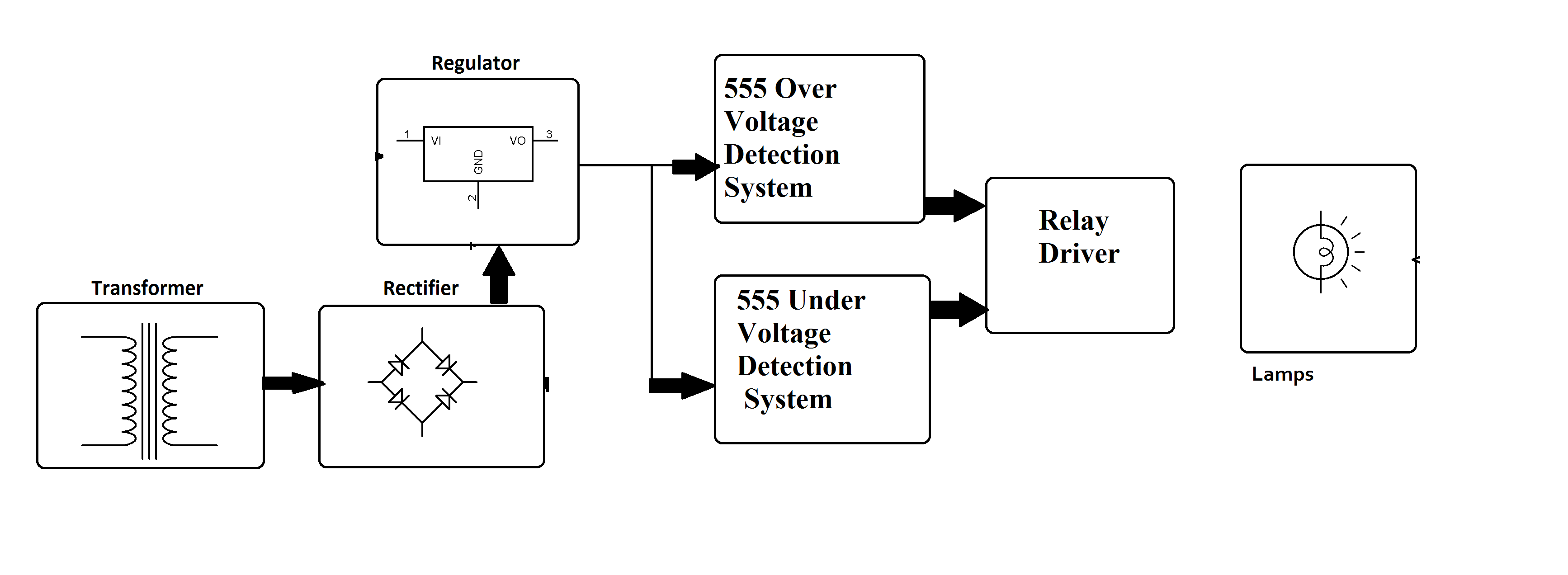
Overvoltage And Undervoltage Protection System
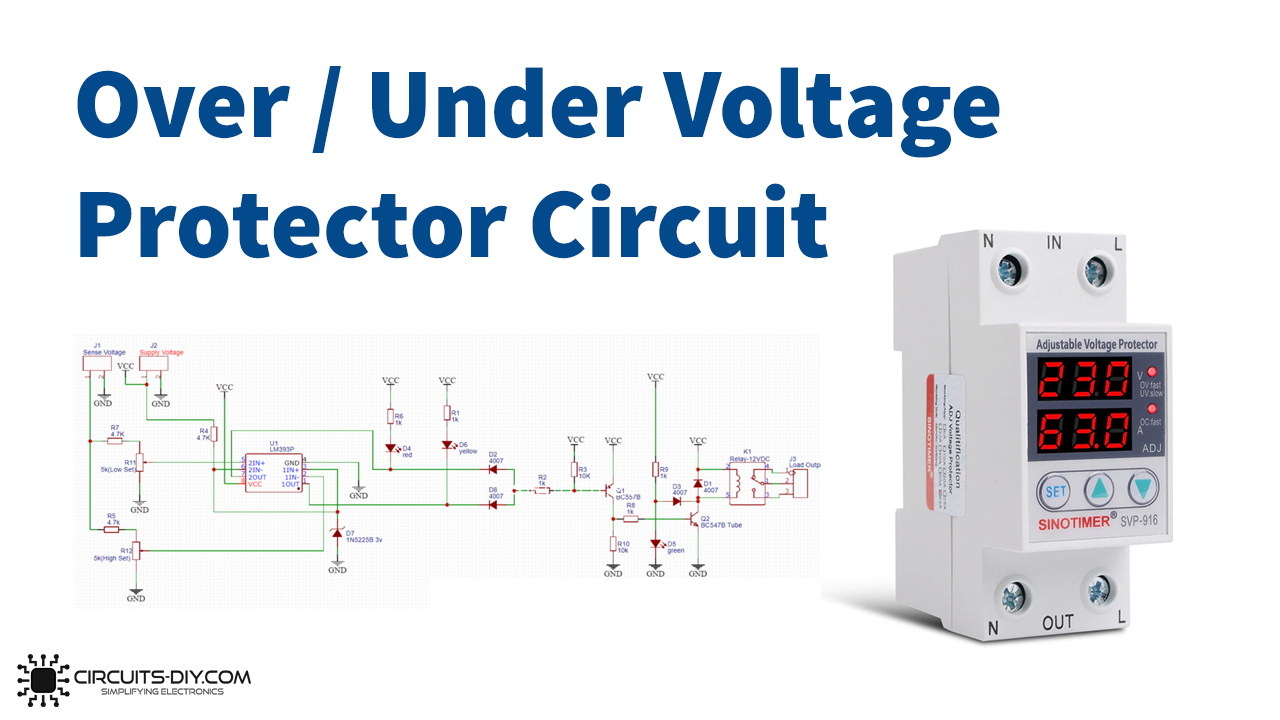
1. Under and Over Voltage Protection Circuit Using Comparators This voltage protection circuit is designed to develop a low-voltage and high-voltage tripping mechanism to protect a load from any damage. In many of the homes and industries fluctuations in AC mains supply take place frequently.
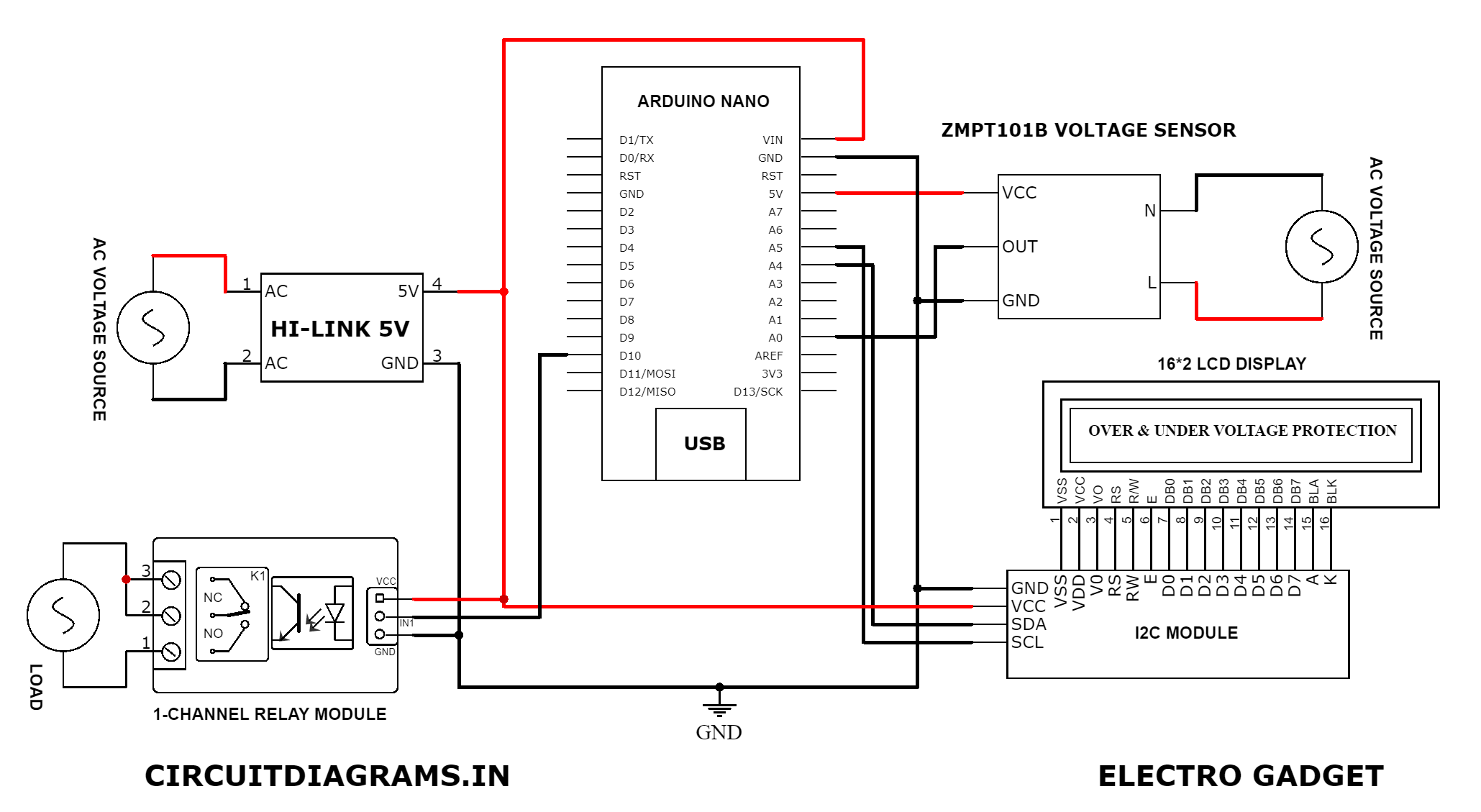
Arduino Based Overvoltage And Undervoltage Protection System
Figure 4 shows the modified schematic that provides overvoltage protection, undervoltage protection, and discharge overcurrent protection for two cells in series. The concept is simple: the alert signal will be logic high when there is no fault condition and logic low when there is a fault condition either on the INA300 or the BQ296xxx. If an.

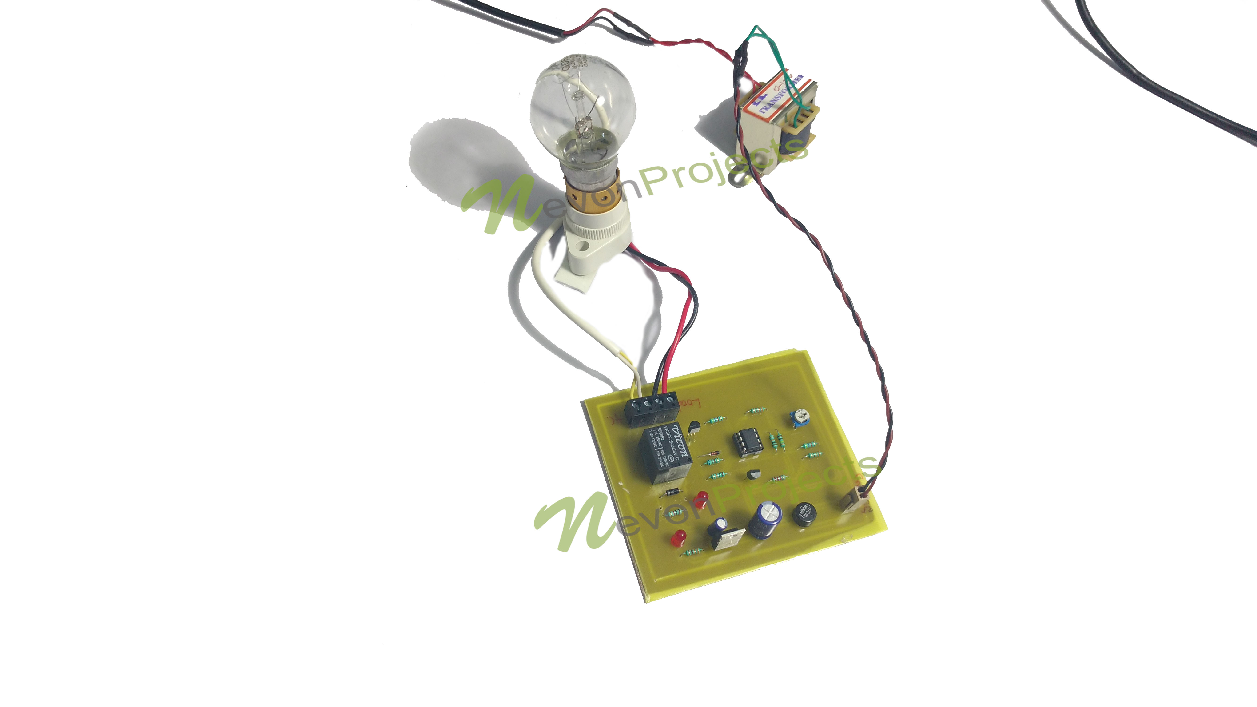
Over Voltage Protection Circuit Diagram For AC Appliances
Undervoltage lockout (UVLO) prevents the downstream electronic system from operating with abnormally low power supply voltages, which could cause system malfunction. For example, digital systems can behave erratically or even freeze up when their supply voltage is below specification.

Undervoltage/Overload Protection 5V KNACRO Digital Voltage Comparator 0
Overvoltage And Undervoltage Protection System December 2018 Authors: Mohit Mishra Rajiv Kumar Saw Deepak Harpreet Kaur Abstract and Figures The sudden change in voltage is huge issue in.
undervoltage release circuit diagram Wiring Diagram and Schematics
Li-Ion Battery Undervoltage Lockout Figure 1 shows an ultralow power, precision undervoltage-lockout circuit. The circuit monitors the voltage of a Li-Ion battery and disconnects the load to protect the battery from deep discharge when the battery voltage drops below the lockout threshold.
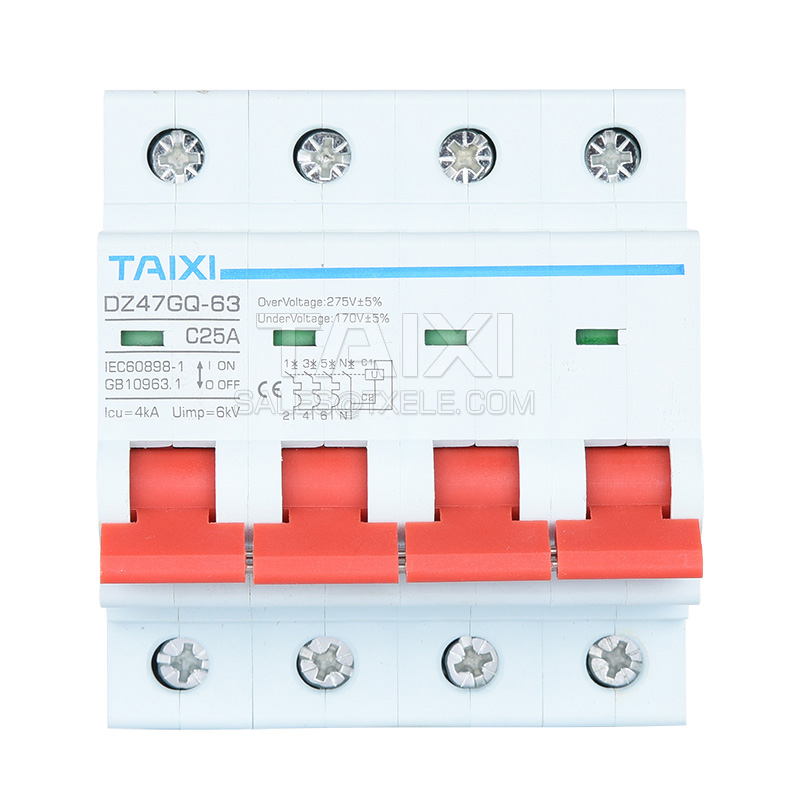
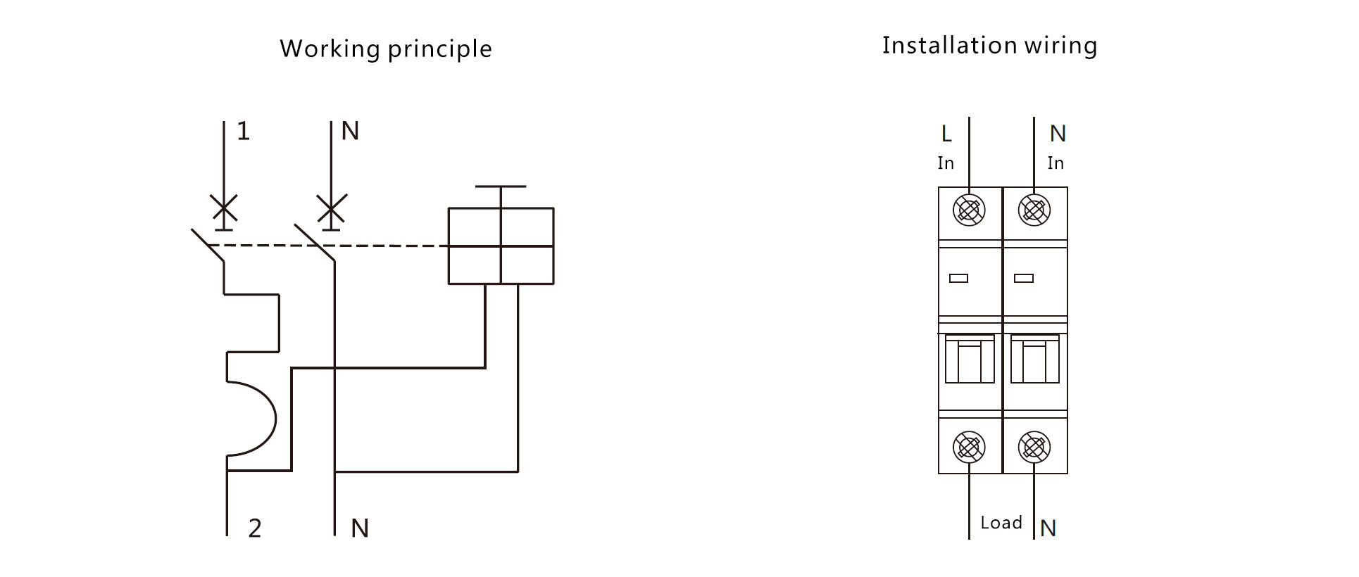
Undervoltage And Overvoltage Protection Circuit Breaker TAIXI Electric
Overvoltage & Under Voltage Protection Circuit Working Explanation This Overvoltage and Under Voltage Protection Circuit needs two input voltages, the first is the 12V that is used to run the whole circuitry and the other is the variable voltage utilized to comprehend if the voltage is high or low.
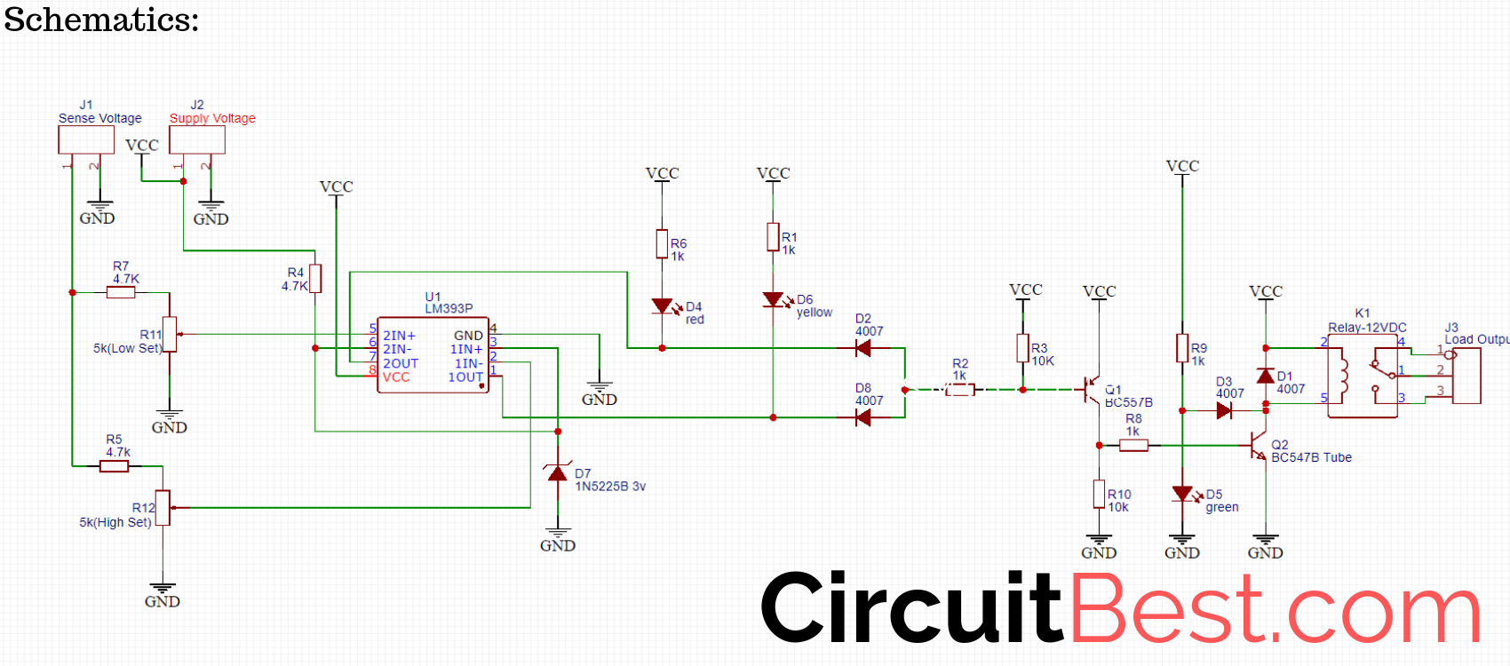
Over voltage and Under Voltage Protection schematics CircuitBest
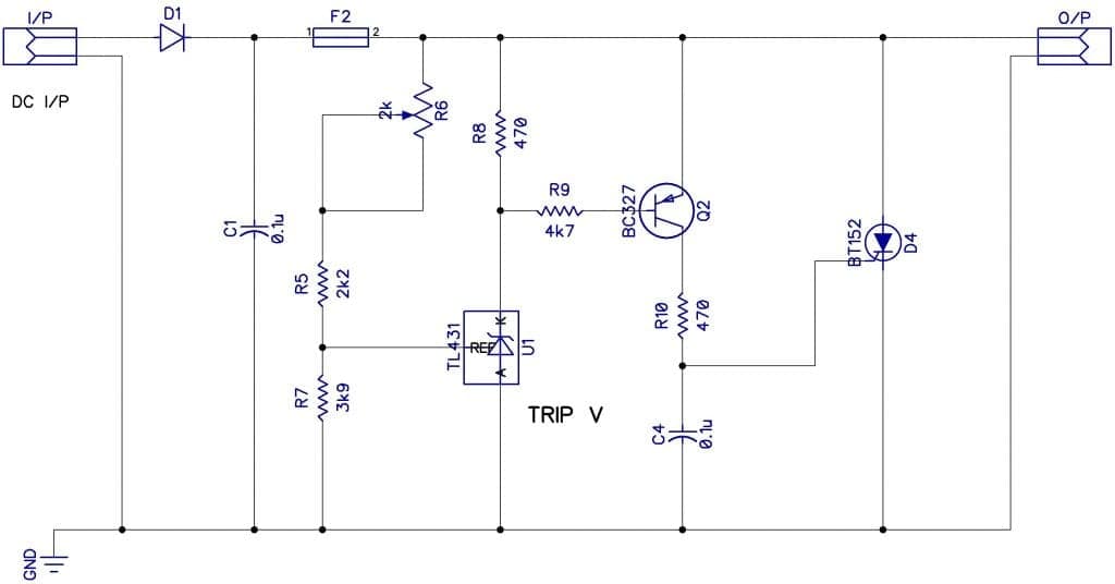
Part 1 - TL431 Undervoltage Protection. I mount this circuit on my breadboard using an IRF4905 MOSFET. I connect a load at the output and supply the circuit at 3V but the load is still OFF. I start increasing the input voltage and as you can see, while the input is below 7.5V the current value is 0 because the ouput is OFF.
Protection Circuits Cloud Information and Distribution
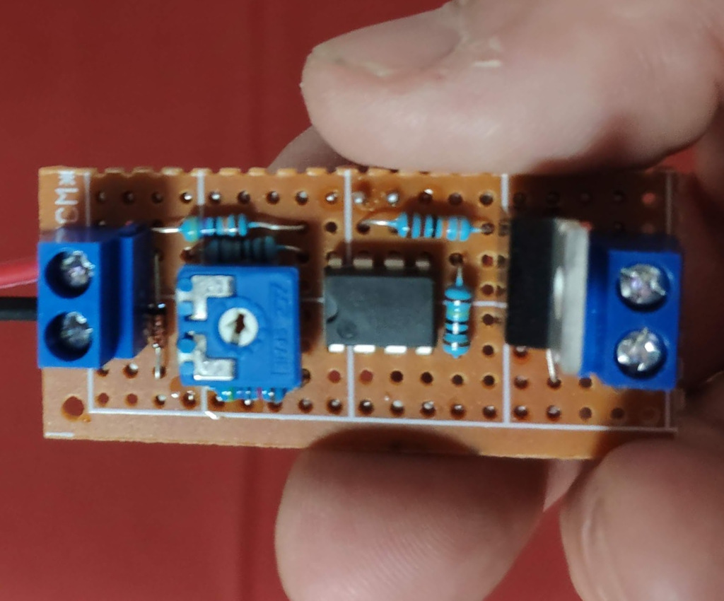
So it is important to use overvoltage and undervoltage protection for electrical and electronic appliances. This circuit incorporates a low-voltage and high-voltage tripping mechanism to protect the appliances from any damage due to voltage fluctuation. The author's prototype on the breadboard is shown in Fig. 1.

Undervoltage Protection Board Undervoltage Switch Error ?0.1V Control
Based on the high voltage BCD technology, an undervoltage protection circuit is designed and implemented. The circuit uses the reference core to realize the detection function of the power supply voltage. It has the characteristics of high accuracy, adjustable detection and adjustable hysteresis window. The circuit is simple in structure and easy to integrate. It can be widely used in high.
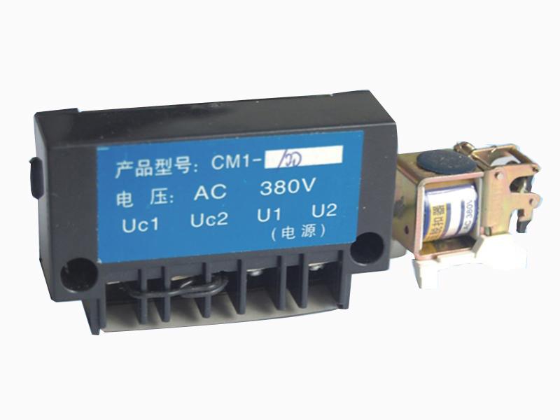
Undervoltage release trip unit MCCB Circuit breaker component DADA
Design Description This undervoltage, protection circuit uses one comparator with a precision, integrated reference to create an alert signal at the comparator output (OUT) if the battery voltage sags below 2.0 V. The undervoltage alert in this implementation is ACTIVE LOW.
Undervoltage And Overvoltage Protection Circuit Breaker TAIXI Electric
18 What is the simplest way to regulate the min DC voltage in a circuit? Is it possible to do with zener diodes? Desired performance: Input > 3.3 VDC Output = Input Input = 3.3 VDC Output = Input Input < 3.3 VDC Output = 0. protection undervoltage Share Cite Follow edited Nov 3, 2010 at 4:44 endolith 28.7k 24 119 184 asked Oct 7, 2010 at 17:57
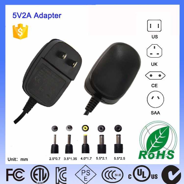
Undervoltage protection circuit of power adapter_Merry King Technology
Basically, under-voltage protection is nothing but a circuit board that is placed between the mains and the batteries, which is capable of detecting any under-voltage condition. This protection device can easily check the phase-to-phase voltage of the power supply device. It used an instrument transformer to do so.
Overvoltage And Undervoltage Protection System
Protection Circuitry. Lithium ion/polymer batteries are extremely power dense. This makes them great for reducing size and weight of projects. However, they are not 'safe' batteries and require extra care. Charging or using the batteries incorrectly can cause explosion or fire (as shown by this and many other youtube videos).

Complete 12V Automotive Undervoltage, Overvoltage and ReverseSupply
Undervoltage protection monitors either three phase-to-phase voltages ( ), or three phase-to-neutral voltages ( V1NV2N, V3N ). ANSI 27-1: each voltage is monitored independently. The protection picks up when one of three monitored voltages reaches the threshold Vmin1. ANSI 27-2: the three voltages are monitored together.
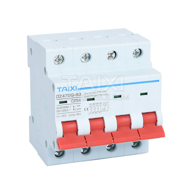
Undervoltage And Overvoltage Protection Circuit Breaker TAIXI Electric
Abstract. This paper identifies the development of an under voltage and over voltage protection in order to avoid damage in load side. Most of the industries and as well as home appliances are very expensive also more sensitive. This may get damaged due to the instabilities in ac mains supply. It can also lead to losses in the electrical circuit.